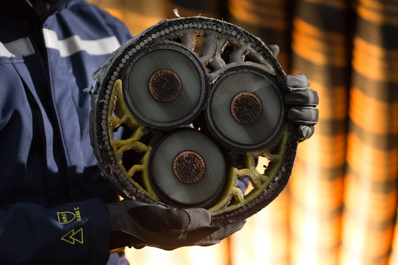

The Crucial Role of Marlinks’ Thermal Models for Subsea Power Cables
In the offshore wind energy sector, subsea power cables play a crucial role in efficiently transmitting electricity from offshore turbines to the shore. At Marlinks, ...
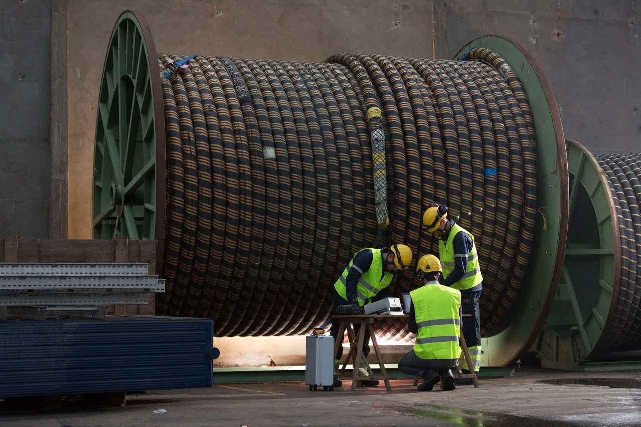
Marlinks Secures First Cable Condition Monitoring Contract in the US
Marlinks, a world leader in the provision of subsea cable integrity monitoring services, announces its first contract award in the United States. The contract includes ...

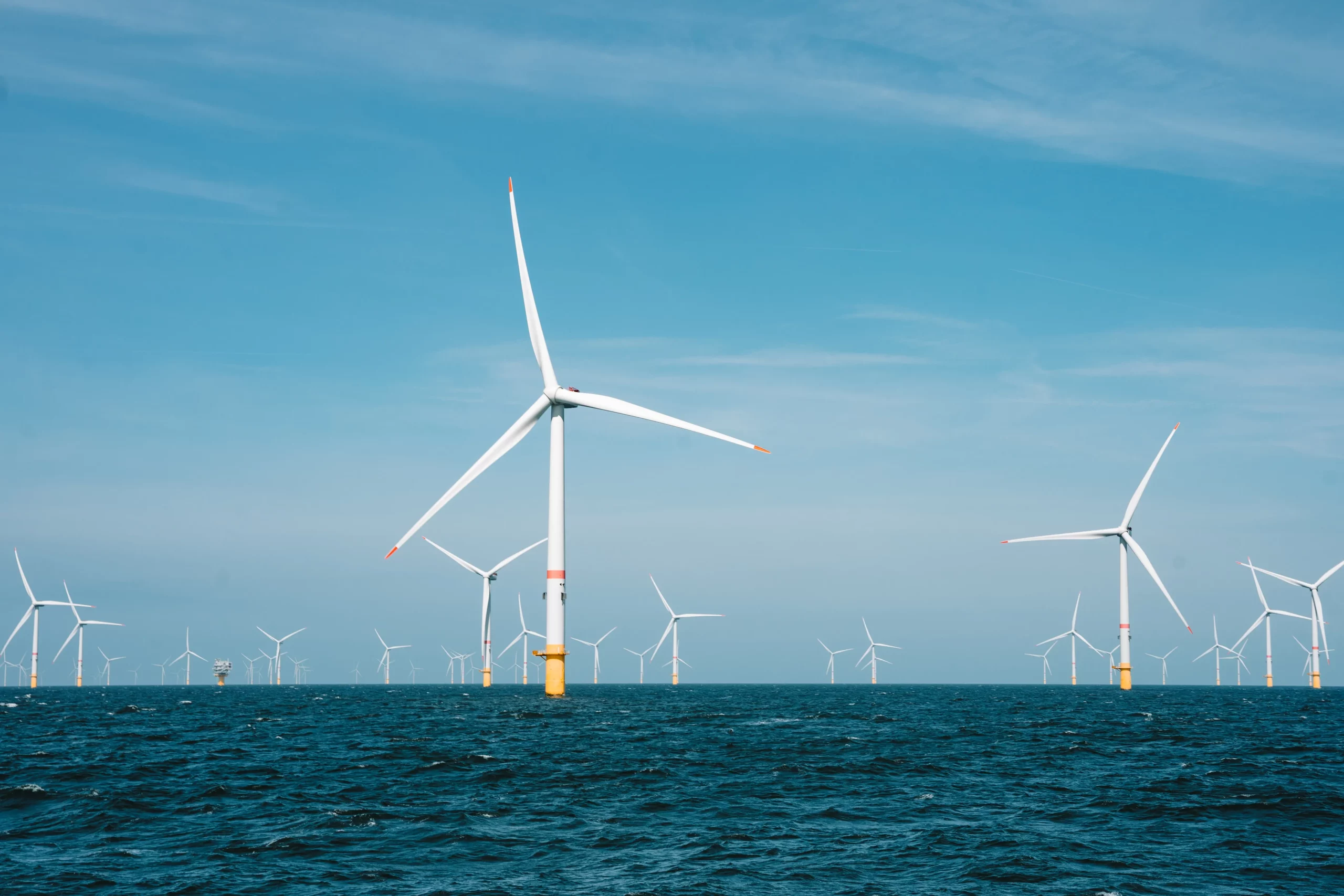
Explore Marlinks’ Dashboard for Real-Time Cable Insights
Subsea cable monitoring is not just a technological advancement. It's a critical component for the operational success and sustainability of offshore wind farms.
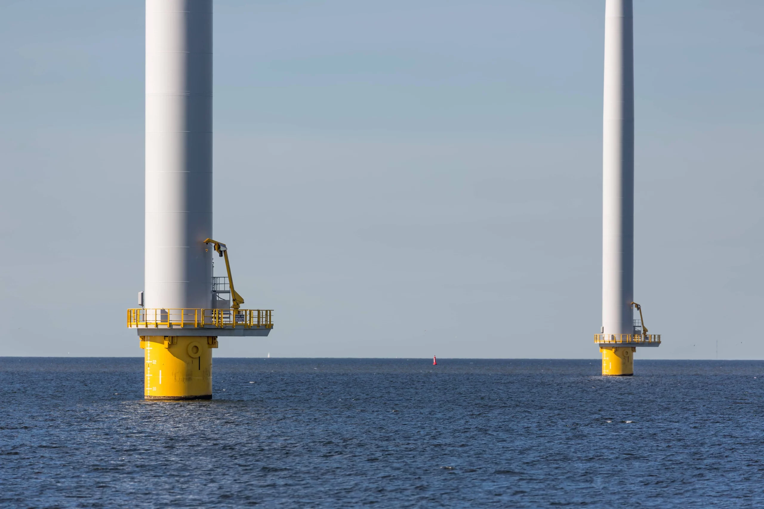
UK’s Offshore Wind Dreams Dashed as Government’s Auction Round 5 Goes Unclaimed
In what is seen by many as a major setback to the UK’s net-zero ambitions, the UK government received no bids for offshore wind projects ...
Meet Our New Business Developer for the UK and US, Andrew Lloyd
Last month Marlinks had the pleasure to onboard Andrew Lloyd, our new UK Business Development Manager, who comes with a vast experience in the power ...