Quality management in fiber optic monitoring.

Cable health monitoring through fiber optics technology significantly reduces manual offshore interventions and allows for a continuous oversight of the health status of the subsea cables. However, for optimal system performance, a meticulously executed fiber optic path is essential. As splicing and connecting of fiber optics on windfarm level is commonly performed by a subcontractor different from Marlinks, we would like to attribute this article to all stakeholders involved in this part of the process, going from splicing experts to developers and operators. Because knowledge is power, and power brings green energy!

Different types of fibers

Optical fibers work on the principle of total reflection, where the initial laser pulse gets partly backscattered due to the structure of the fiber optic. The spectrum of the backscattered light tells more about the temperate or strain (change) at certain locations along the fiber.  

The choice of fiber type significantly influences the optical loss per distance. Given the long distances typically encountered in offshore wind applications, single mode fibers are commonly preferred due to their lower optical loss compared to multimode fibers. However, it’s worth noting that single mode fibers and equipment entail higher costs, often five times or more than multimode fibers. Additionally, we advise against mixing single mode and multimode fibers within the same project and their respective equipment setups. 

Splicing vs Connectors

Splices have a preference over connectors in offshore wind since they will have lower optical losses at the jointing points. However, connecting connectors is easier executed than splicing two fibers together since it requires expertise and equipment.  

In offshore wind, we prefer APC (Angled Physical Contact) connectors over UPC (Ultra Polished Contact) connectors since they reduce the unwanted backscatter at the end of the fiber due to their angled connector point compared to other types of connectors which have a flat connecting point. 

It’s essential to note that this distinction pertains to minimizing unwanted backscatter, distinct from the desired backscatter occurring within the fiber optic due to its internal structure. As a best practice, it’s advisable to avoid mixing different types of connectors within a single fiber optic sensing design. 

Optical losses and optical budget

The optical loss along the fiber trajectory should stay less than the optical budget, which is the maximum loss the DTS or DAS device can allow before it won’t be able to reach the full trajectory anymore of the fiber. However, as there are many contractor parties involved in the works concerning fiber optic cable laying and splicing/ connecting, Marlinks highly recommends the end-client to verify the requirements, communicate to and manage the cable contractor to ensure the requirements are met. Both the cable contractor and substation contractor can provide evidence of compliance through independent OTDR (Optical Time Domain Reflectometer) measurements. This collaborative approach ensures that the optical system meets the specified requirements for optimal performance. 

Termination units & Best practises

Termination units dampen the signal at the end of a fiber trajectory, ensuring the unwanted backscatter stays limited. Finally, unclean connectors stand out as one of the most prevalent issues impacting the quality of readings from DTS and DAS devices. Ensuring proper cleaning and inspection using a fiber optics microscope can significantly mitigate the need for subsequent corrective measures. Additionally, adopting the practice of covering connectors with dust caps and leaving them in place until connection is required serves as an effective preventive measure against connector contamination. By implementing these best practices, potential disruptions caused by dirty connectors can be minimized, contributing to the reliability and accuracy of data obtained from DTS and DAS devices. 

Want to learn more?

You can reach us by sending a message to sales@marlinks.com and we’ll be happy to schedule a conversation to discuss.

Highlighted news

engineer installing optical fibers at substation

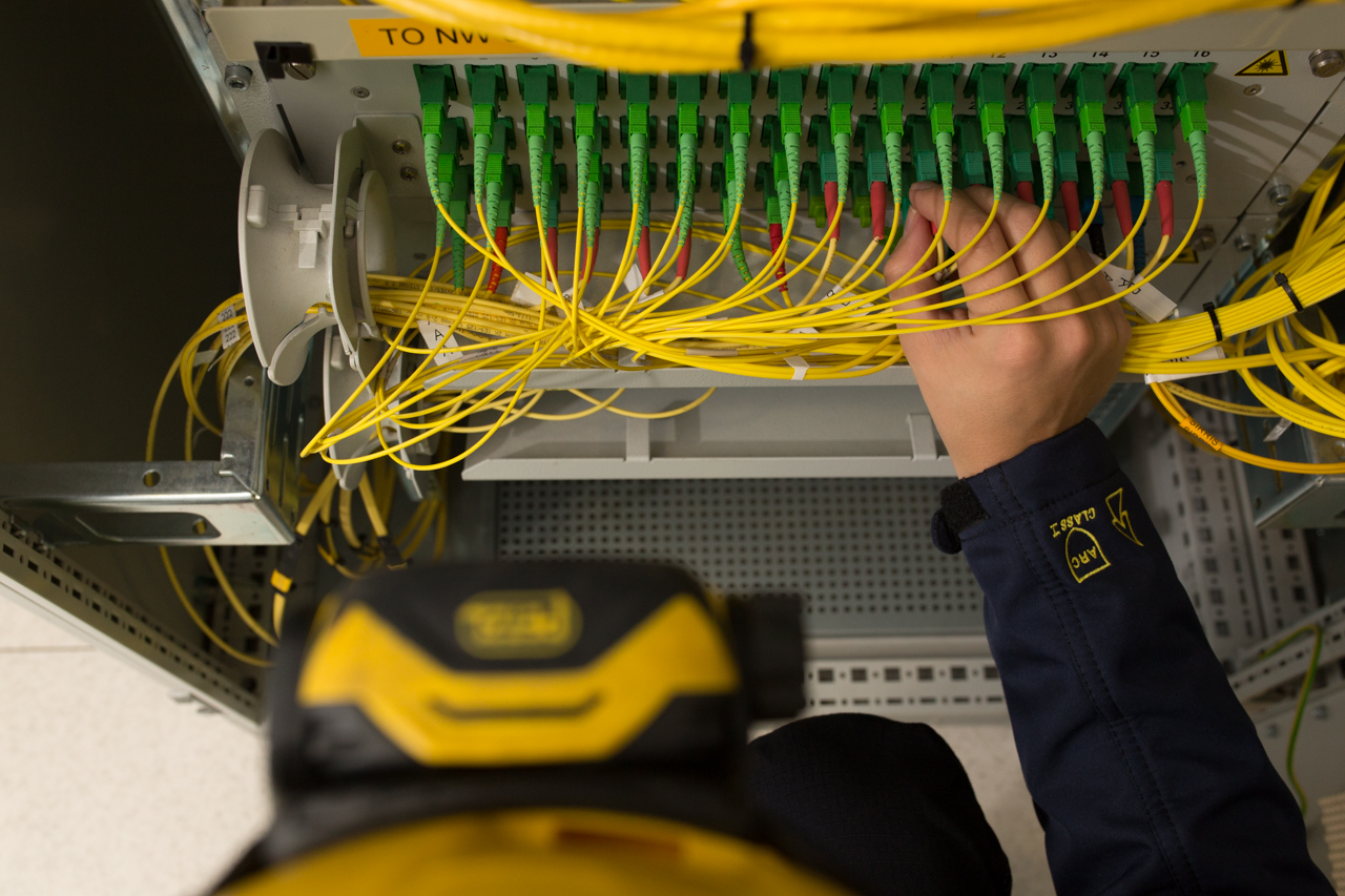
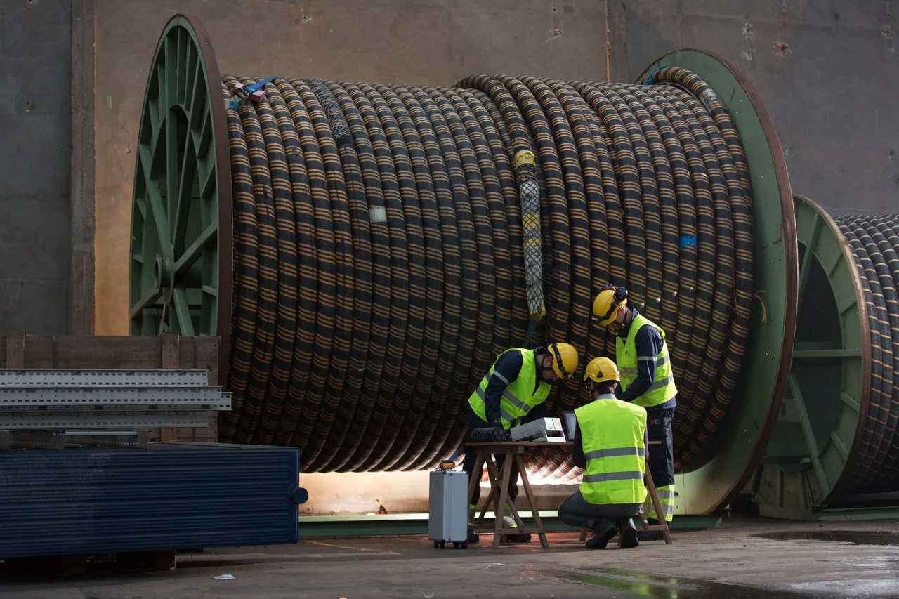
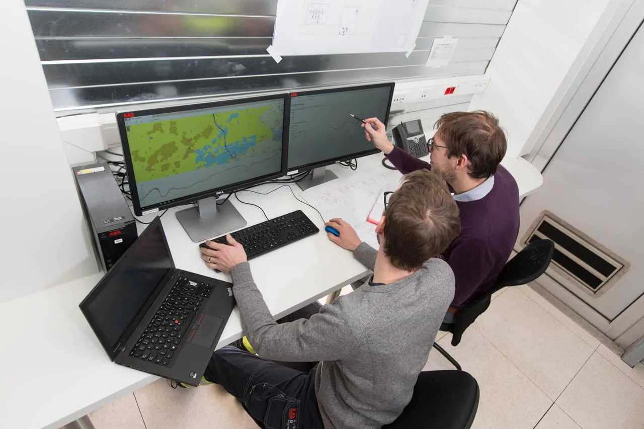
From Raw Subsea Cable Data to Actionable Insights

Our goal at Marlinks is to turn data into actionable insights. In a nutshell, this means as a starting point we verify and enhance the ...
Read More
andy readyhough

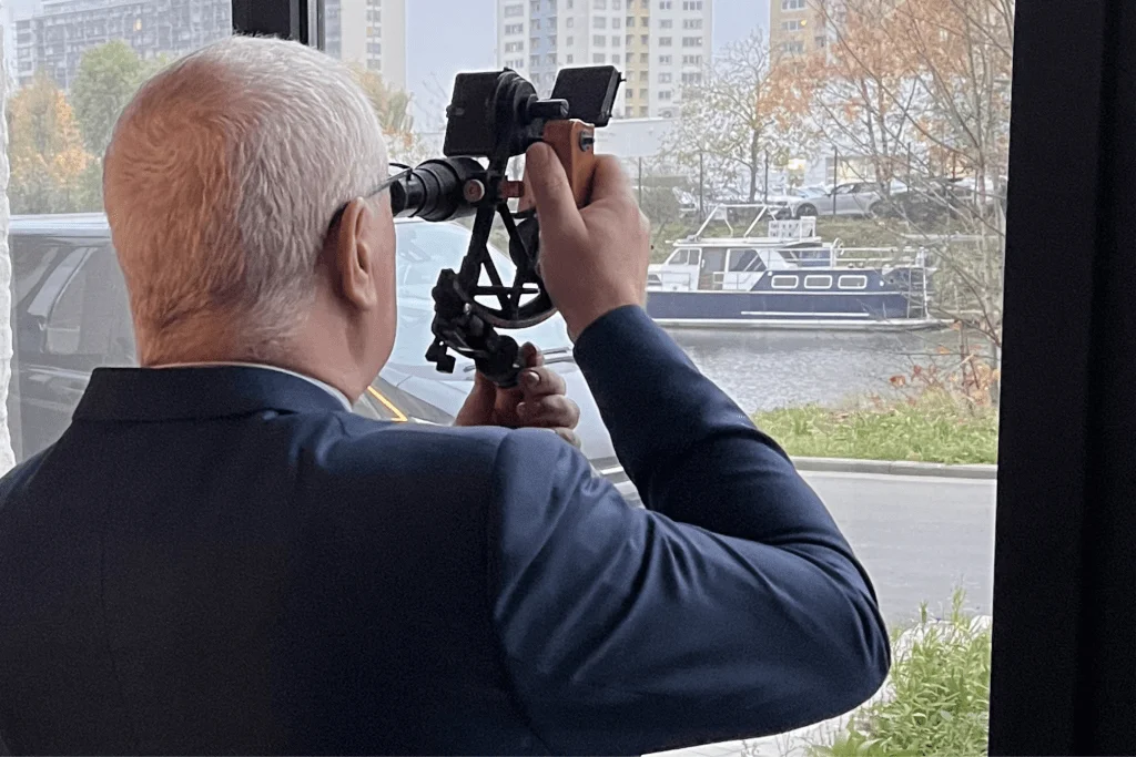
Our UK Brand Ambassador, Andy Shares Some Last Thoughts Before Going into Retirement

Our UK brand ambassador has seen the offshore wind market evolve from its early stages and left a considerable mark on the whole industry. However, ...
Read More
three people monitor subsea power cable on big reel with fiber optic technology

The Crucial Role of Marlinks’ Thermal Models for Subsea Power Cables

In the offshore wind energy sector, subsea power cables play a crucial role in efficiently transmitting electricity from offshore turbines to the shore. At Marlinks, ...
Read More
two persons analysing subsea cable data

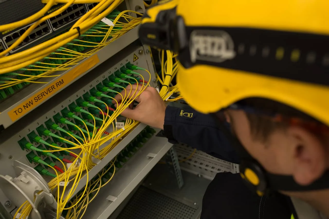
6 Reasons Why Subsea Cable Monitoring is Essential for Offshore Wind Farms

Subsea cable monitoring is not just a technological advancement. It's a critical component for the operational success and sustainability of offshore wind farms.
Read More

Why a Customized Cable Monitoring Approach Brings You the Best Results

At Marlinks we believe designing a cable condition monitoring systems for the offshore wind industry always needs to be tailored to the specifics of a ...
Read More
Scroll to Top